F250 accelerator problem
#1
Hi, we have a 2005 F250 with a 5,4 engine. While driving the accelerator quits working. The engine just idles and will not rev up. If we pull the number 22 ECM fuse in the passenger compartment fuse box the engine will die. Then replace the fuse and everything is fine for awile.
Has anyone had this problem?
Thanks in advance for any help.
Has anyone had this problem?
Thanks in advance for any help.
#2
Evidently, what the PCM powers has a problem, and when you pull the fuse the PCM resets and everything is fine until the problem shows up .
Do you have any kind of electrical test equip to use ?
EXACTLY what are you doing when driving that the problem shows up ?
The PCM (powertrain computer),supplies many sensors and it helps if we had some idea to where to look for the problem.
If the problem appears after you do a certain thing, that helps eliminate a lot of unnecessary testing.
There may or may not be a code in the computer to assist with the diagnosis.
Last edited by hanky; 04-11-2024 at 08:21 AM.
#3
I'm not driving the truck. It is my stepsons. He is just driving normal on local trips that he takes to work and such so nothing out of the ordinary as far I know.
I do have some test equipment, Older Snap -On that I can get some data and some other testers, VOM and such.
I'm not a Ford tech but do understand a bit about the system. I've worked on a few. I'm a retired GM tech.
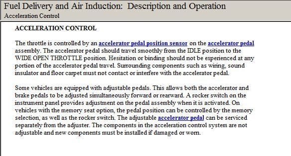
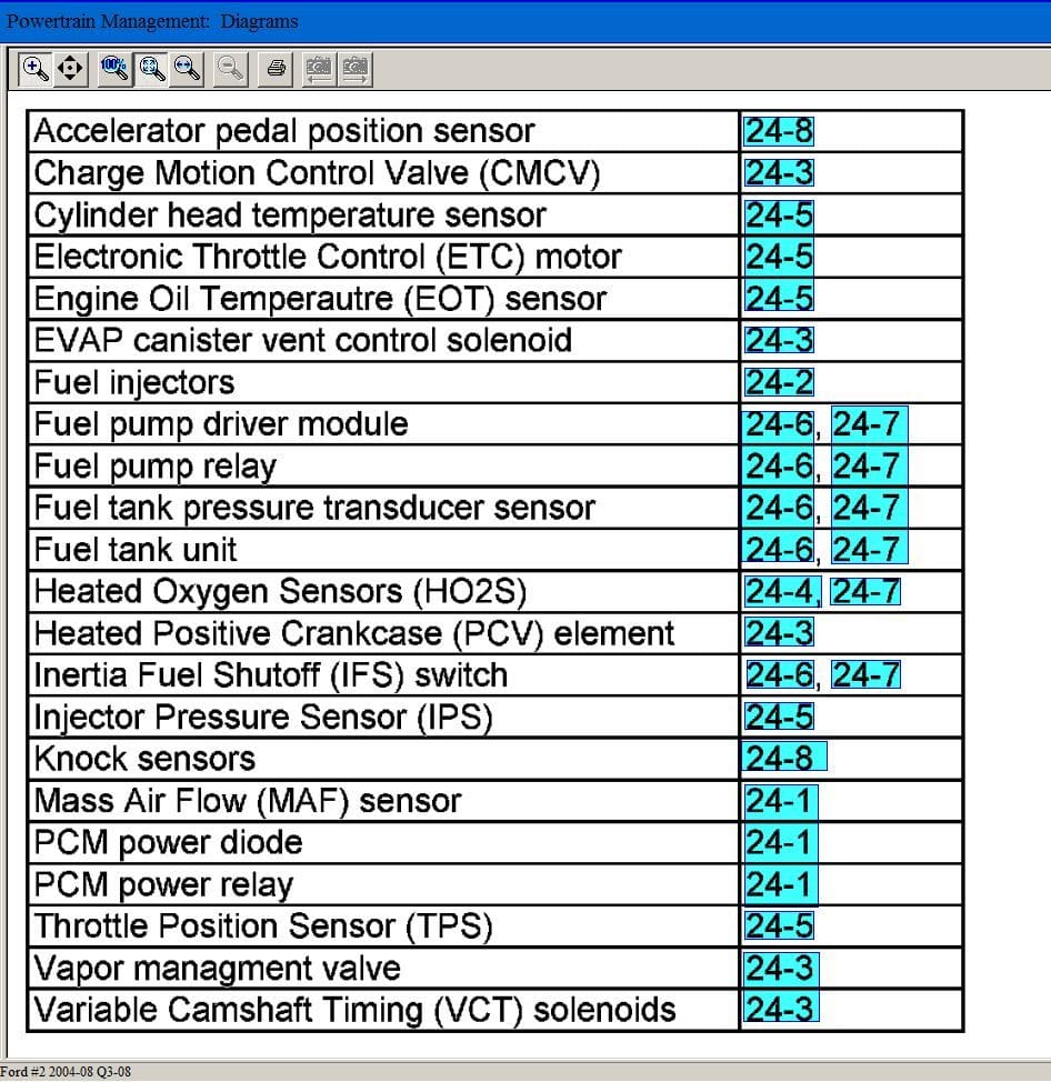
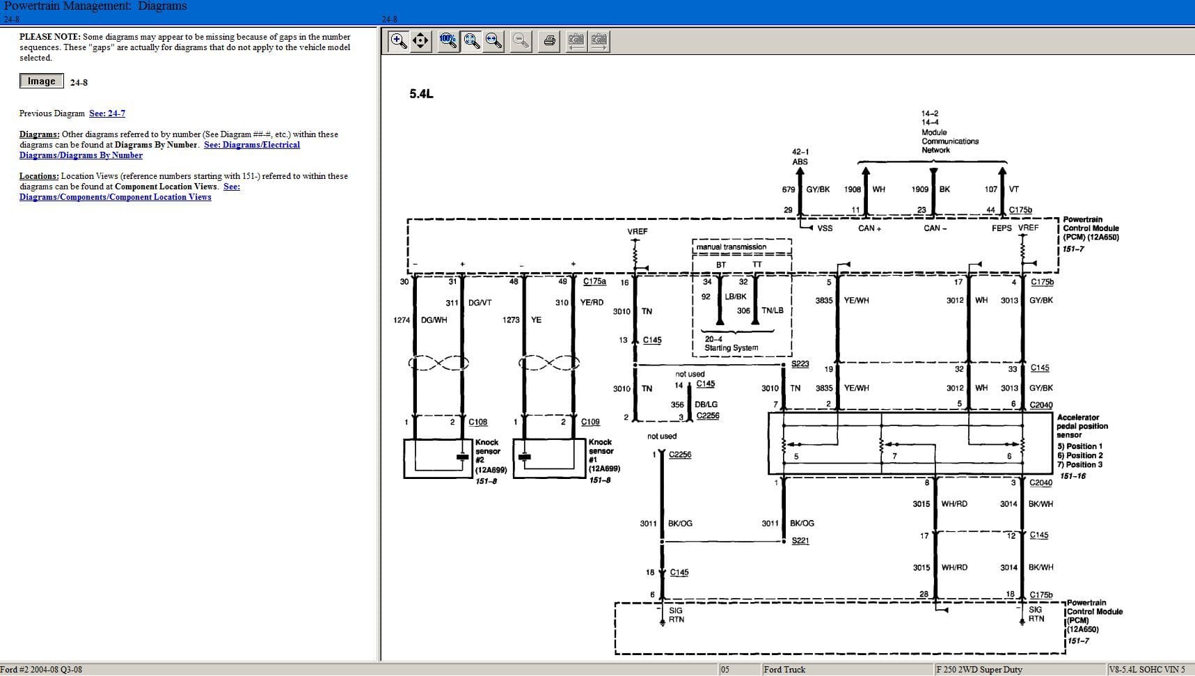
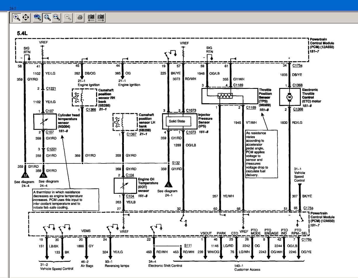
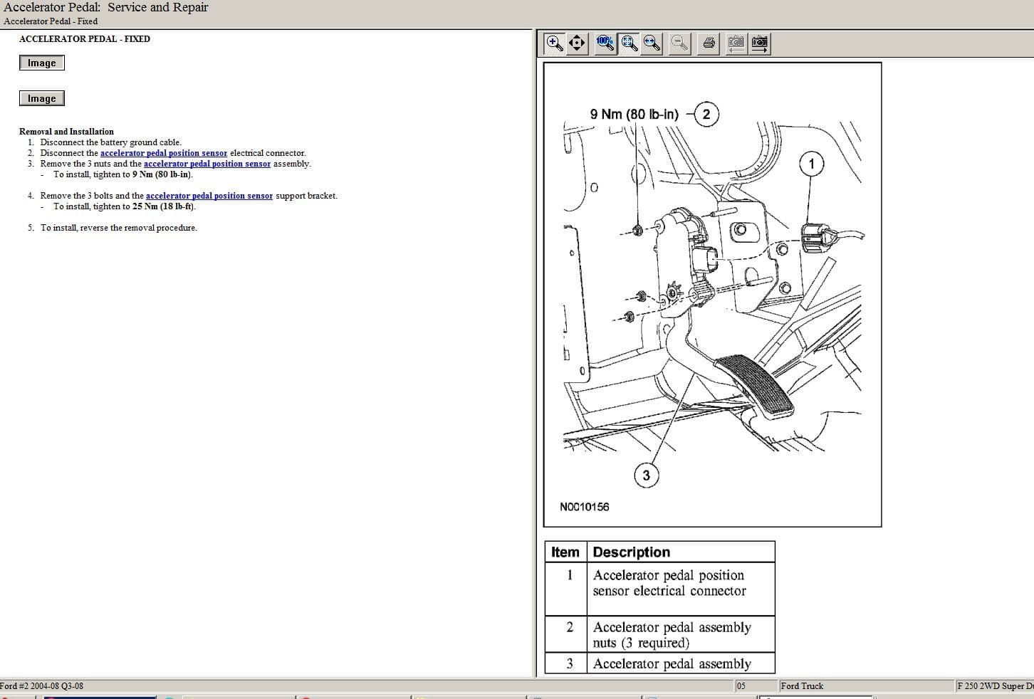
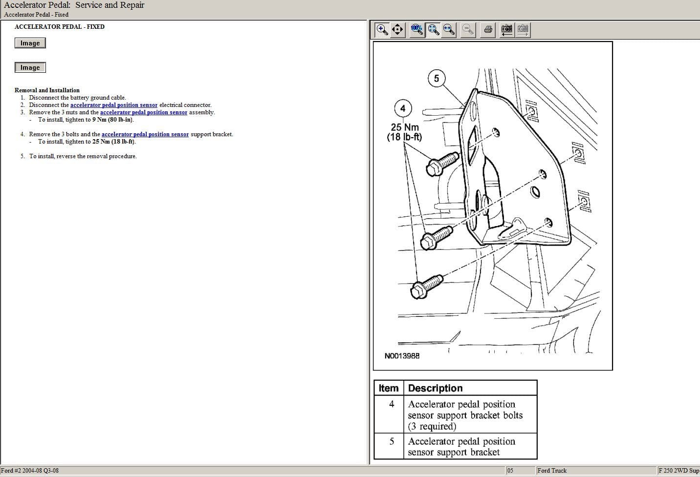
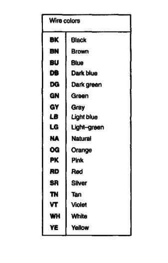
What I'd like to have is the ECM/PCM connector and accelerator system diagrams. Our local Dealership changed hands a while back and the new owners are not fond of helping others.
I haven't had a chance to scan anything yet. I do know that the problem happened Sunday night because he called me and I told him to check for blown fuses and that is when we discovered it would reset . Now it happens every few miles then will be ok for a while so I'm not ready to blame the wiring, I'm leaning towards PCM
#7
Thanks for the diagrms, they will help. I might be able to check it out this weekend. I haven't seen the truck since the day this problem appeared. I'm going to try to scan it.
I would like to do a snapshot of the data lines when the problem happens but my scanner won't do it. So I'm going to try a couple other tests.
I would like to do a snapshot of the data lines when the problem happens but my scanner won't do it. So I'm going to try a couple other tests.
#8
Unlike the drive-by-cable cars, your drive-by-wire truck you just need to scan and see what's going on. If you need another diagram please let me know. Like above I provided only 24-5 and 24-8. Don't forget to check the 5 pdf attachments too. And don't pull the ECM fuse if at all possible we all know it can do major damage to your ECM.
#9
I'm familiar with drive by wire and most other systems. I was a General Moters tech from 1970 untill 2012 or so, mostly Chevrolet then an everything but Chevy dealer. Caddilac, Buick, Pontiac, Oldsmobile and GMC.
Thanks again for the diagrams and I may need more. I won't know until I can get a reading on the pedal position sensor and a couple other things. I do have a spare whole engine wiring harness from a 5.4 that I just rebuilt so I have that covered for connectors if need be.
Thanks again for the diagrams and I may need more. I won't know until I can get a reading on the pedal position sensor and a couple other things. I do have a spare whole engine wiring harness from a 5.4 that I just rebuilt so I have that covered for connectors if need be.
#10
Keep in mind the PCM provides the reference voltage to all the sensors and it can be absent, provided with a unintended path to ground thru a possibly shorted sensor, or even a poor connection at a sensor.
If any one of the sensors it provides power to is shorted to ground, it will bring that power to all on the circuit down where none will function correctly or not at all.
The fun part is finding which sensor or maybe a wire with a poor connection OR rubbed thru enough to cause a partial short and make finding it quite a challenge.
The diagrams Heiko provides are appreciated and very helpful, thanks for the help.


