
Five Hundred Center Dash Clock Schematics Help


Thread Starter
|
Junior Member
Joined: Nov 2015
Posts: 24
Hello again everyone,
As some of you may already know, some of the interior of my SE has been upgraded and that includes the addition of the center dash analog clock. When I purchased the trim the dash trim came with the clock included minus the clock connector which I had to purchase from Ford separately. When I received the connector from Ford all the wires were black.
Can someone please help me with the color, number of wires and location of the wires coming off the clock? A detailed picture would be just as helpful.
Any help is greatly appreciated.
Thank you!

Senior Member
Joined: Jun 2010
Posts: 16,613
How many wires did the connector have ?
It could have had 3 or 4 wires , 2 of which were the + & - for the clock and either one or two for the interior light on the clock. If it only had 3 wires that would mean the clock and lite shared a common ground. If you look closely at the back of the clock you might see a + and - sign over the terminals and that would make the hook-up much easier. Can you check that and let us know if any marks are present?
It could have had 3 or 4 wires , 2 of which were the + & - for the clock and either one or two for the interior light on the clock. If it only had 3 wires that would mean the clock and lite shared a common ground. If you look closely at the back of the clock you might see a + and - sign over the terminals and that would make the hook-up much easier. Can you check that and let us know if any marks are present?

Thread Starter
|
Junior Member
Joined: Nov 2015
Posts: 24
How many wires did the connector have ?
It could have had 3 or 4 wires , 2 of which were the + & - for the clock and either one or two for the interior light on the clock. If it only had 3 wires that would mean the clock and lite shared a common ground. If you look closely at the back of the clock you might see a + and - sign over the terminals and that would make the hook-up much easier. Can you check that and let us know if any marks are present?
It could have had 3 or 4 wires , 2 of which were the + & - for the clock and either one or two for the interior light on the clock. If it only had 3 wires that would mean the clock and lite shared a common ground. If you look closely at the back of the clock you might see a + and - sign over the terminals and that would make the hook-up much easier. Can you check that and let us know if any marks are present?


Senior Member
Joined: Jun 2010
Posts: 16,613
Looking at the plug, it shows only 4 numbers and it appears the center terminals are not used.
We know the lite in the clock runs off a wire from any one of the dash lights since it should be allowed to dim as desired.
You do not have to do this, but I would run a 12 volt supply to one of the terminals and ground the other in the same line of the pins/plug like #1 &4 or 3 & 6.The light will lite when you connect the correct terminals, and the clock will either run or not at which point you might reverse the wires so the connections are correct then the second hand should move in the correct direction. The resistance of the light bulb will prevent any possible direct short circuit if the light wires are not in the right place , should not be a problem.
Just be careful when connecting the 12 volt supply to anything so that the end of the wire does not touch any grounded metal. (best to use a fuse in that wire in the event it slips and manages to contact any grounded surface) Depending on how long the leads are on the plug you may even be able to do the check right at the battery posts.
Thread Starter
|
Junior Member
Joined: Nov 2015
Posts: 24
Looking at the plug, it shows only 4 numbers and it appears the center terminals are not used.
We know the lite in the clock runs off a wire from any one of the dash lights since it should be allowed to dim as desired.
You do not have to do this, but I would run a 12 volt supply to one of the terminals and ground the other in the same line of the pins/plug like #1 &4 or 3 & 6.The light will lite when you connect the correct terminals, and the clock will either run or not at which point you might reverse the wires so the connections are correct then the second hand should move in the correct direction. The resistance of the light bulb will prevent any possible direct short circuit if the light wires are not in the right place , should not be a problem.
Just be careful when connecting the 12 volt supply to anything so that the end of the wire does not touch any grounded metal. (best to use a fuse in that wire in the event it slips and manages to contact any grounded surface) Depending on how long the leads are on the plug you may even be able to do the check right at the battery posts.
We know the lite in the clock runs off a wire from any one of the dash lights since it should be allowed to dim as desired.
You do not have to do this, but I would run a 12 volt supply to one of the terminals and ground the other in the same line of the pins/plug like #1 &4 or 3 & 6.The light will lite when you connect the correct terminals, and the clock will either run or not at which point you might reverse the wires so the connections are correct then the second hand should move in the correct direction. The resistance of the light bulb will prevent any possible direct short circuit if the light wires are not in the right place , should not be a problem.
Just be careful when connecting the 12 volt supply to anything so that the end of the wire does not touch any grounded metal. (best to use a fuse in that wire in the event it slips and manages to contact any grounded surface) Depending on how long the leads are on the plug you may even be able to do the check right at the battery posts.
There are only 4 numbers to identify wires and their direction or order if you will. For example the terminal labeled 1 corresponds to wire no. 1 the next one that is unnumbered would be no. 2, how do I know that? Because the next terminal is terminal no. 3. The one under no.1 is no. 4 thus making the next unnumbered is 5...how? Because the next one is...you got it...6!

I have been able to use a 9v battery to get the clock to work. But what I'm looking for is for some to either provide me with a picture of their wires behind their clock so I can see the color of the wires and be able to determine their actual function.
Senior Member
Joined: Jun 2010
Posts: 16,613
When you hooked up the 9 v battery to the clock, did you have the battery + (pos) terminal connected to #4 wire on your plug and the battery - (neg) connected to terminal #3 on the plug ?
If not try that set up, If that allows it to work we can go from there.
If not try that set up, If that allows it to work we can go from there.
Thread Starter
|
Junior Member
Joined: Nov 2015
Posts: 24
When I initially did this test I was able to kinda figure out some wires but to this day I am not really sure if I got them in the right order or designation but this is what I got.
1. I got nothing
2. can't make out writing, may be Illum
3. Ground
4. HOT 1
5. I got nothing
6. HOT 2
And that is why I need verification as to what is really what. But now that I think about it 1, 3 and 5 may be grounds to the proceeding wires. Still, I need verification to the even number wires.
1. I got nothing
2. can't make out writing, may be Illum
3. Ground
4. HOT 1
5. I got nothing
6. HOT 2
And that is why I need verification as to what is really what. But now that I think about it 1, 3 and 5 may be grounds to the proceeding wires. Still, I need verification to the even number wires.
Senior Member
Joined: Jun 2010
Posts: 16,613
I believe it is safe to assume that term # 1 & 5 are not used.
Some vehicles come through with the harness wires present just not used.
Check behind the clock area if you can see a plug with the following color wires,
Blue
Black/orange
Orange/yellow
Black
Usually, Ford uses blk/orange as batt +
Black=ground
The other colors can be for illumination control
Looks like your making good progress , ya gotta do a little detective work sometimes !
Thread Starter
|
Junior Member
Joined: Nov 2015
Posts: 24
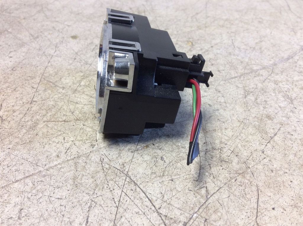
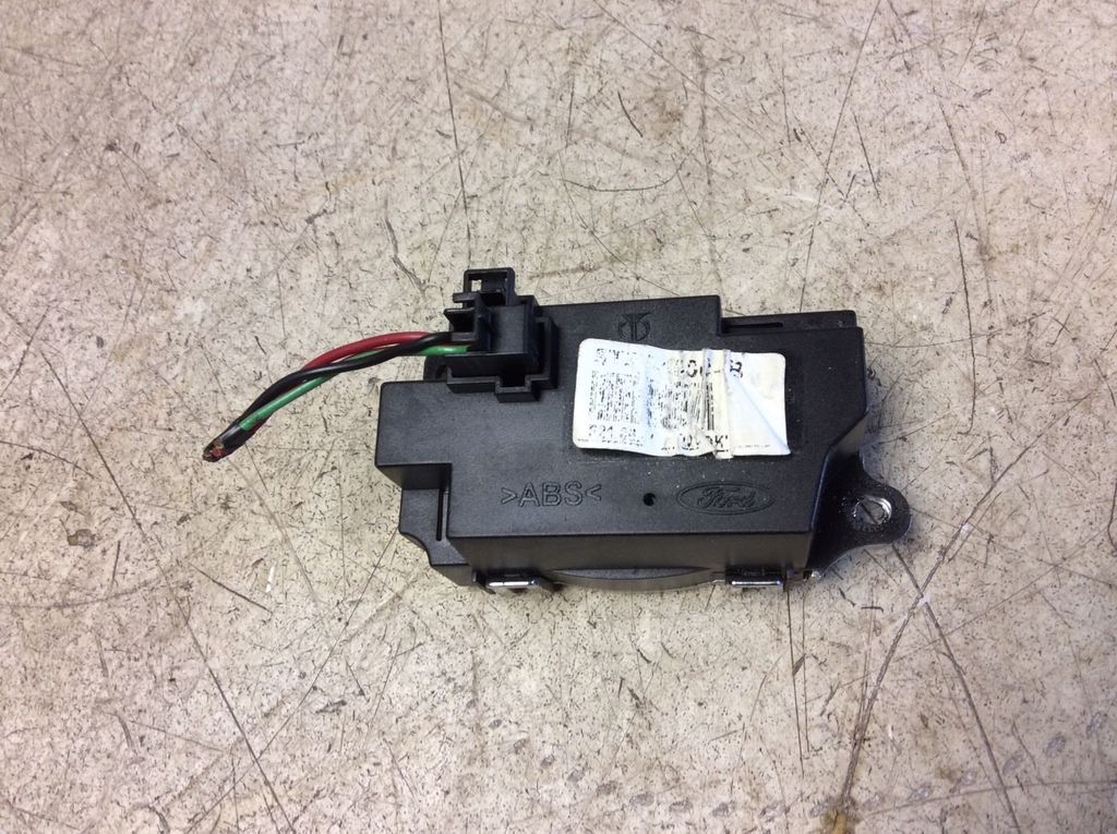
Ok so I repeated what I did the first time I tried to do this and I don't know why it took me so long to revisit this step. I took a trip to flebay and looked for a clock that had wires sticking out from the back, compared it to a wiring diagram I found after hours of searching (can be found under the horn or cigarette lighter schematic diagram) and bam! Found exactly what I wanted!
I hope this helps anyone else looking to do what I did with my interior. One step closer to SEL status. Lets see how close I can get to LIMITED status Thank you for the help Hanky.
Diagram says
2. Illum LG-RD
3. GRND BK
6. PWR RD
On to the pictures!
I hope this helps anyone else looking to do what I did with my interior. One step closer to SEL status. Lets see how close I can get to LIMITED status
Thank you for the help Hanky.Diagram says
2. Illum LG-RD
3. GRND BK
6. PWR RD
On to the pictures!


Thread
Thread Starter
Forum
Replies
Last Post