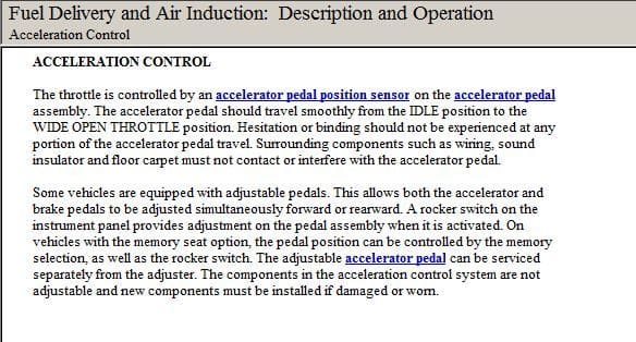
F250 accelerator problem
#11
Do you have the connector diagrams for the connectors on the left fender well and the ones for the underhood fuse box. I don't want to start throwing parts at this thing. I had a throttle body from another 5.4 that was left over from a 5.4 that i rebuilt for a friends 2006 f350 last year. I kept the intake and related parts and the wiring harness
#14
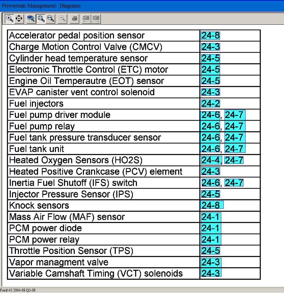
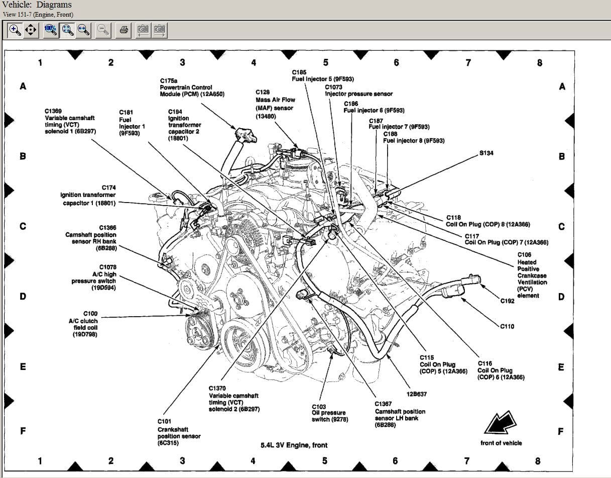
Thanks these help a lot. Do you have all of the PCM connector views? 175 ABC?
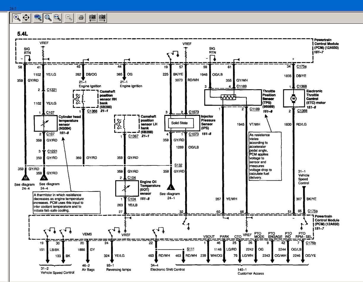
When I run a KOEO scan I get code P2104 which is one I have been getting, plus P2122, P2127 and P2132.
When the problem first started he was pulling the PCM fuseand putting it back in. That would reset the system and he could drive for a while. I told him that doing that wasn't a great idea as It is a shock to the system.
I I've done a wiggle test, cleaned the throttle body, battery terminals, and several grounds. Now it works if I unplug the #175 connectors at the PCM and reconnect them all is well for a while. I'm leaning towards a bad /weak female pin in a connector, a ground or such. I don't want to blame any hard parts or PCM yet as it seems like a connector overheat situation or such. ( PCM internal overheat?) My experiance with connector heat is that 20 minutes is the average time for 12 volts steady draw. For internal PCM/ECM pull up or pull down 5 volt or 5 volt refrence I'm not sure . Any thoughts?
#16
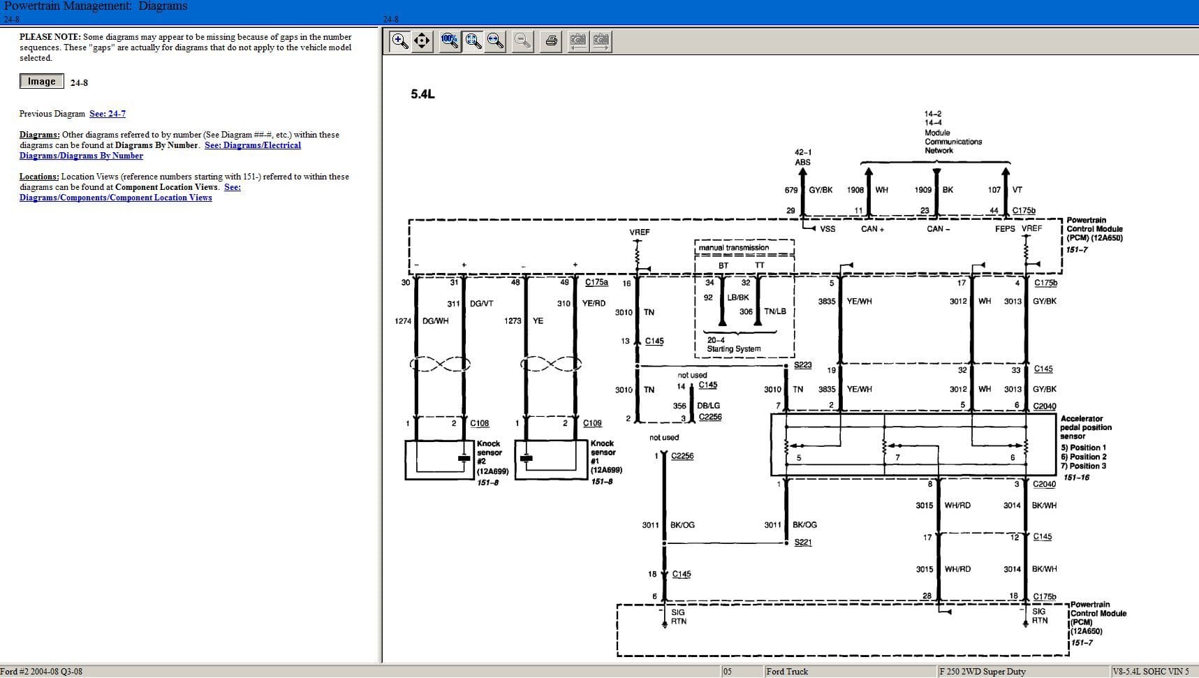
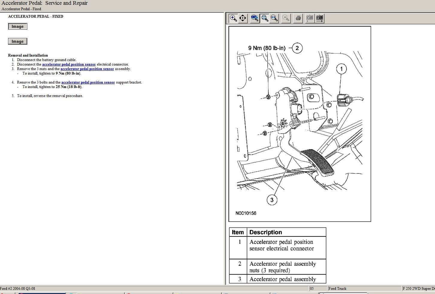
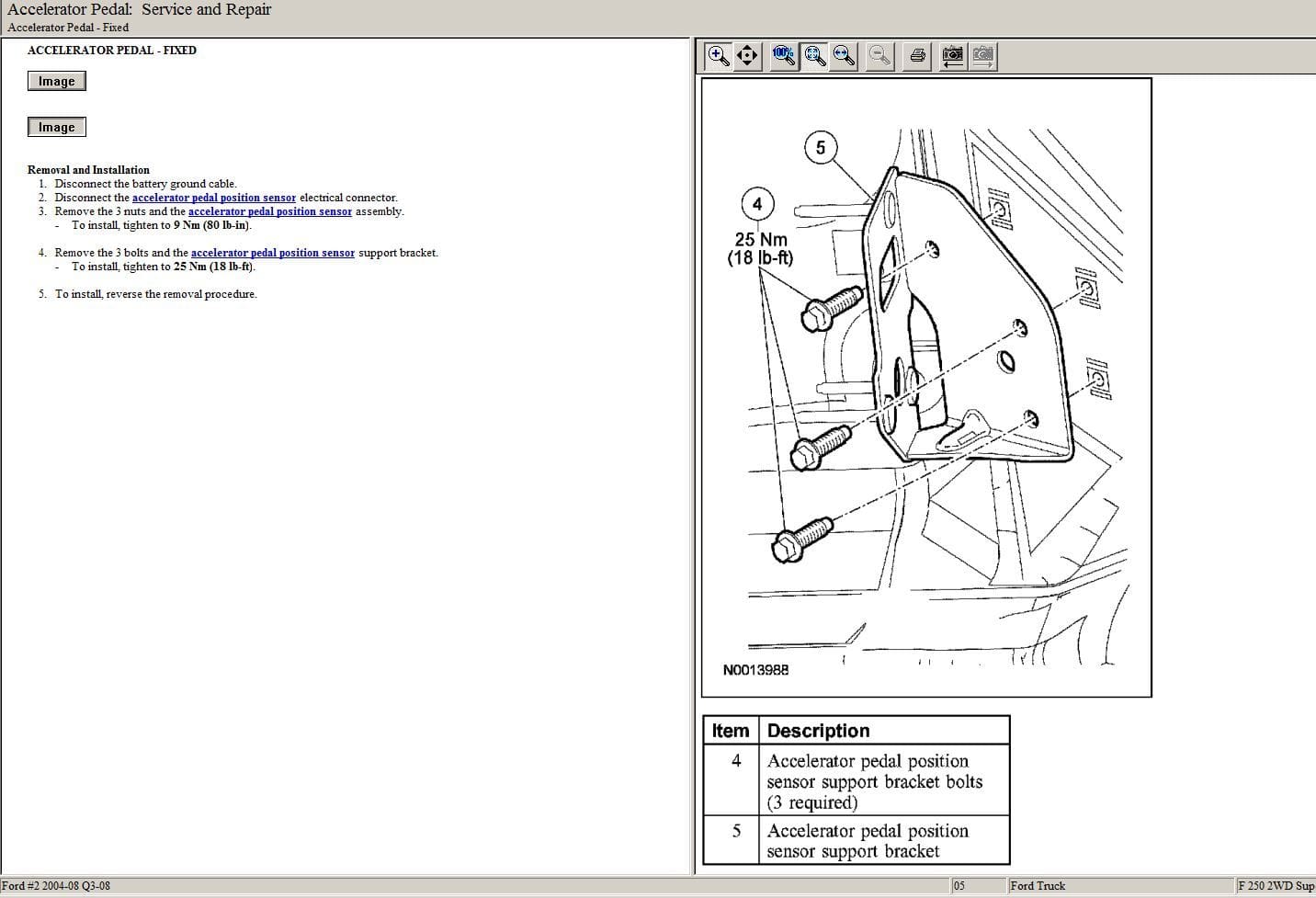
I would like 175 a and b alsk if you have them. I might have found the trouble in the accelerator position wiring. At the moment I'm ok if im not pressed to the floor hard. If i press it hard to the floor I ho into forced idle. Also if I just touch the harness to the sensor it goes to forced idle. The first time I looked at the truck I saw that the wiring tape was frayed from Bigfoot syndrome and asked him about it because he has a bad foot from being hit by a car and wears size 12 boots. I couldn't find anything then but I have a VOM and a Power Probe and will check my resistance. Could you please let me know the reference wire voltage, 5?? and the expected resistance across the sensors if it is available.
#17
175A and 175B diagrams already enclosed previously as inline attachments above, look at the upper left of the diagram to locate.
I'm still trying to look for circuit 3010 (TN) and give you the voltage reference, too many pages to go over.
I'm still trying to look for circuit 3010 (TN) and give you the voltage reference, too many pages to go over.
#18
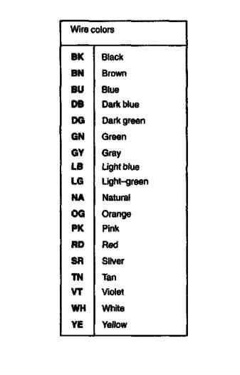
Circuit 3010 (TN)
C175B-pin16 -> C145-pin13 -> S223 -> C2040-pin7
Go to: https://www.powerstrokenation.com/th....153082/page-2
Look at #29 Zmann mentioned alldata (my software) has specs on the voltage reference.
Look at #35 at https://www.powerstrokenation.com/th....153082/page-2 for the reference.
C175B-pin16 -> C145-pin13 -> S223 -> C2040-pin7
Go to: https://www.powerstrokenation.com/th....153082/page-2
Look at #29 Zmann mentioned alldata (my software) has specs on the voltage reference.
Look at #35 at https://www.powerstrokenation.com/th....153082/page-2 for the reference.
#19
[QUOTE=heiko;141408]175A and 175B diagrams already enclosed previously as inline attachments above, look at the upper left of the diagram to locate.
I'm still trying to look for circuit 3010 (TN) and give you the voltage reference, too many pages to go over.[/QUOTE
I found bad wires at the accelerator sensor. I replaced three bug am going to replace the other four. All bad ones are internal breaks with the insulation smashed where someone with large feet stepped on them. It is storming here at the moment or I would have replaced them all tonight.
I'll let you know the outcome, just hoping that all the on/off hasn't damaged the PCM.
Thread
Thread Starter
Forum
Replies
Last Post


